华为交换机配置MSTP功能
组网需求
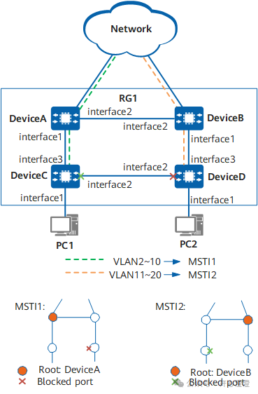
如图1-31所示,网络中DeviceA、DeviceB、DeviceC和DeviceD之间存在环路。用户希望在网络中部署MSTP,破除网络环路,从而避免广播风暴和MAC表振荡;并且实现VLAN2~VLAN10和VLAN11~VLAN20的流量负载分担。
图1-31 配置MSTP功能组网图

本例中interface1、interface2、interface3分别代表10GE1/0/1、10GE1/0/2、10GE1/0/3。
操作步骤
- 配置DeviceA、DeviceB、DeviceC和DeviceD到域名为RG1的域内,创建实例MSTI1和实例MSTI2。
当两台设备的MST域的域名、实例和VLAN的映射关系、MST域的修订级别都相同时,这两台设备属于同一个MST域。
不能将同一个VLAN映射到多个不同的实例上。如果将一个已经和实例建立映射关系的VLAN又映射到另一个实例上,原来的映射关系将被取消。
# 在DeviceA上配置MST域。
<HUAWEI> system-view
[HUAWEI] sysname DeviceA
[DeviceA] stp region-configuration
[DeviceA-mst-region] region-name RG1
[DeviceA-mst-region] instance 1 vlan 2 to 10
[DeviceA-mst-region] instance 2 vlan 11 to 20
[DeviceA-mst-region] quit
# 在DeviceB上配置MST域。
<HUAWEI> system-view
[HUAWEI] sysname DeviceB
[DeviceB] stp region-configuration
[DeviceB-mst-region] region-name RG1
[DeviceB-mst-region] instance 1 vlan 2 to 10
[DeviceB-mst-region] instance 2 vlan 11 to 20
[DeviceB-mst-region] quit
# 在DeviceC上配置MST域。
<HUAWEI> system-view
[HUAWEI] sysname DeviceC
[DeviceC] stp region-configuration
[DeviceC-mst-region] region-name RG1
[DeviceC-mst-region] instance 1 vlan 2 to 10
[DeviceC-mst-region] instance 2 vlan 11 to 20
[DeviceC-mst-region] quit
# 在DeviceD上配置MST域。
<HUAWEI> system-view
[HUAWEI] sysname DeviceD
[DeviceD] stp region-configuration
[DeviceD-mst-region] region-name RG1
[DeviceD-mst-region] instance 1 vlan 2 to 10
[DeviceD-mst-region] instance 2 vlan 11 to 20
[DeviceD-mst-region] quit
2. 在MST域RG1内,分别配置MSTI1、MSTI2的根桥和备份根桥。
# 配置DeviceA为MSTI1的根桥。
[DeviceA] stp instance 1 root primary
# 配置DeviceB为MSTI1的备份根桥。
[DeviceB] stp instance 1 root secondary
# 配置DeviceB为MSTI2的根桥。
[DeviceB] stp instance 2 root primary
# 配置DeviceA为MSTI2的备份根桥。
[DeviceA] stp instance 2 root secondary
3. 配置同一网络内所有设备的端口路径开销应使用相同的计算方法;配置实例MSTI1和MSTI2中将要被阻塞端口的路径开销值大于缺省值。
# 配置DeviceA的端口路径开销计算方法为华为计算方法。
[DeviceA] stp pathcost-standard legacy
# 配置DeviceB的端口路径开销计算方法为华为计算方法。
[DeviceB] stp pathcost-standard legacy
# 配置DeviceC的端口路径开销计算方法为华为计算方法,将端口10GE1/0/2在实例MSTI2中的路径开销值配置为20000。
[DeviceC] stp pathcost-standard legacy
[DeviceC] interface 10ge 1/0/2
[DeviceC-10GE1/0/2] portswitch
[DeviceC-10GE1/0/2] stp instance 2 cost 20000
[DeviceC-10GE1/0/2] quit
# 配置DeviceD的端口路径开销计算方法为华为计算方法,将端口10GE1/0/2在实例MSTI1中的路径开销值配置为20000。
[DeviceD] stp pathcost-standard legacy
[DeviceD] interface 10ge 1/0/2
[DeviceD-10GE1/0/2] portswitch
[DeviceD-10GE1/0/2] stp instance 1 cost 20000
[DeviceD-10GE1/0/2] quit
4. 设备全局启用MSTP。缺省情况下,设备上生成树协议处于使能状态,无需操作。在系统视图下执行命令stp enable可以启用STP/RSTP/MSTP功能。5. 在设备与终端相连的端口上去使能MSTP。# 在DeviceC端口10GE1/0/1上去使能MSTP功能。
[DeviceC] interface 10ge 1/0/1
[DeviceC-10GE1/0/1] portswitch
[DeviceC-10GE1/0/1] stp disable
[DeviceC-10GE1/0/1] quit
# 在DeviceD端口10GE1/0/1上去使能MSTP功能。
[DeviceD] interface 10ge 1/0/1
[DeviceD-10GE1/0/1] portswitch
[DeviceD-10GE1/0/1] stp disable
[DeviceD-10GE1/0/1] quit
6. 配置保护功能,如在各实例的根桥设备的指定端口配置根保护功能。
# 在DeviceA端口10GE1/0/1上启动根保护。
[DeviceA] interface 10ge 1/0/1
[DeviceA-10GE1/0/1] portswitch
[DeviceA-10GE1/0/1] stp root-protection
[DeviceA-10GE1/0/1] quit
# 在DeviceB端口10GE1/0/1上启动根保护。
[DeviceB] interface 10ge 1/0/1
[DeviceB-10GE1/0/1] portswitch
[DeviceB-10GE1/0/1] stp root-protection
[DeviceB-10GE1/0/1] quit
7. 创建VLAN并将接口加入VLAN。
# 在DeviceA上创建VLAN2~20,并将DeviceA的端口10GE1/0/1和10GE1/0/2分别加入VLAN。
[DeviceA] vlan batch 2 to 20
[DeviceA] interface 10ge 1/0/1
[DeviceA-10GE1/0/1] portswitch
[DeviceA-10GE1/0/1] port link-type trunk
[DeviceA-10GE1/0/1] port trunk allow-pass vlan 2 to 20[DeviceA-10GE1/0/1] quit
[DeviceA] interface 10ge 1/0/2
[DeviceA-10GE1/0/2] portswitch
[DeviceA-10GE1/0/2] port link-type trunk
[DeviceA-10GE1/0/2] port trunk allow-pass vlan 2 to 20
[DeviceA-10GE1/0/2] quit
# 在DeviceB上创建VLAN2~20,并将DeviceB的端口10GE1/0/1和10GE1/0/2分别加入VLAN。
[DeviceB] vlan batch 2 to 20
[DeviceB] interface 10ge 1/0/1
[DeviceB-10GE1/0/1] portswitch
[DeviceB-10GE1/0/1] port link-type trunk
[DeviceB-10GE1/0/1] port trunk allow-pass vlan 2 to 20
[DeviceB-10GE1/0/1] quit[DeviceB] interface 10ge 1/0/2
[DeviceB-10GE1/0/2] portswitch
[DeviceB-10GE1/0/2] port link-type trunk
[DeviceB-10GE1/0/2] port trunk allow-pass vlan 2 to 20
[DeviceB-10GE1/0/2] quit
# 在DeviceC上创建VLAN2~20,并将DeviceC的端口10GE1/0/1、10GE1/0/2和10GE1/0/3分别加入VLAN。
[DeviceC] vlan batch 2 to 20
[DeviceC] interface 10ge 1/0/1
[DeviceC-10GE1/0/1] portswitch
[DeviceC-10GE1/0/1] port link-type access
[DeviceC-10GE1/0/1] port default vlan 2
[DeviceC-10GE1/0/1] quit
[DeviceC] interface 10ge 1/0/2
[DeviceC-10GE1/0/2] portswitch
[DeviceC-10GE1/0/2] port link-type trunk
[DeviceC-10GE1/0/2] port trunk allow-pass vlan 2 to 20
[DeviceC-10GE1/0/2] quit
[DeviceC] interface 10ge 1/0/3
[DeviceC-10GE1/0/3] portswitch
[DeviceC-10GE1/0/3] port link-type trunk
[DeviceC-10GE1/0/3] port trunk allow-pass vlan 2 to 20
[DeviceC-10GE1/0/3] quit
# 在DeviceD上创建VLAN2~20,并将DeviceD的端口10GE1/0/1、10GE1/0/2和10GE1/0/3分别加入VLAN。
[DeviceD] vlan batch 2 to 20
[DeviceD] interface 10ge 1/0/1
[DeviceD-10GE1/0/1] portswitch
[DeviceD-10GE1/0/1] port link-type access
[DeviceD-10GE1/0/1] port default vlan 11
[DeviceD-10GE1/0/1] quit
[DeviceD] interface 10ge 1/0/2
[DeviceD-10GE1/0/2] portswitch
[DeviceD-10GE1/0/2] port link-type trunk
[DeviceD-10GE1/0/2] port trunk allow-pass vlan 2 to 20
[DeviceD-10GE1/0/2] quit
[DeviceD] interface 10ge 1/0/3
[DeviceD-10GE1/0/3] portswitch
[DeviceD-10GE1/0/3] port link-type trunk
[DeviceD-10GE1/0/3] port trunk allow-pass vlan 2 to 20
[DeviceD-10GE1/0/3] quit
检查配置结果
在网络计算稳定后,执行以下操作,验证配置结果。本配置举例以实例1和实例2为例,因此不用关注实例0中端口的状态。
# 在DeviceA上执行命令display stp brief,查看端口角色和端口状态。在MSTI1中,由于DeviceA是根桥,DeviceA的端口10GE1/0/2和10GE1/0/1成为指定端口。在MSTI2中,DeviceA的端口10GE1/0/1成为指定端口,端口10GE1/0/2成为根端口。
[DeviceA] display stp brief
MSTID Port Role STP State Protection Cost Edged
0 10GE1/0/1 DESI forwarding root 2 disable
0 10GE1/0/2 DESI forwarding none 2 disable
1 10GE1/0/1 DESI forwarding root 2 disable
1 10GE1/0/2 DESI forwarding none 2 disable
2 10GE1/0/1 DESI forwarding root 2 disable
2 10GE1/0/2 ROOT forwarding none 2 disable
# 在DeviceB上执行命令display stp brief,查看端口角色和端口状态。在MSTI2中,由于DeviceB是根桥,端口10GE1/0/1和10GE1/0/2在MSTI2中成为指定端口。在MSTI1中,DeviceB的端口10GE1/0/1成为指定端口,端口10GE1/0/2成为根端口。
[DeviceB] display stp brief
MSTID Port Role STP State Protection Cost Edged
0 10GE1/0/1 DESI forwarding root 2 disable
0 10GE1/0/2 ROOT forwarding none 2 disable
1 10GE1/0/1 DESI forwarding root 2 disable
1 10GE1/0/2 ROOT forwarding none 2 disable
2 10GE1/0/1 DESI forwarding root 2 disable
2 10GE1/0/2 DESI forwarding none 2 disable
# 在DeviceC上执行命令display stp interface brief,查看端口角色和端口状态。DeviceC的端口10GE1/0/3在MSTI1和MSTI2中为根端口。DeviceC的另一个端口10GE1/0/2,在MSTI2中被阻塞,在MSTI1中被计算为指定端口。
[DeviceC] display stp interface 10ge 1/0/3 brief
MSTID Port Role STP State Protection Cost Edged
0 10GE1/0/3 ROOT forwarding none 2 disable
1 10GE1/0/3 ROOT forwarding none 2 disable
2 10GE1/0/3 ROOT forwarding none 2 disable
[DeviceC] display stp interface 10ge 1/0/2 brief
MSTID Port Role STP State Protection Cost Edged
0 10GE1/0/2 DESI forwarding none 2 disable
1 10GE1/0/2 DESI forwarding none 2 disable
2 10GE1/0/2 ALTE discarding none 20000 disable
# 在DeviceD上执行命令display stp interface brief,查看端口角色和端口状态。DeviceD的端口10GE1/0/3在MSTI1和MSTI2中为根端口。DeviceD的另一个端口10GE1/0/2,在MSTI1中被阻塞,在MSTI2中被计算为指定端口。
[DeviceD] display stp interface 10ge 1/0/3 brief
MSTID Port Role STP State Protection Cost Edged
0 10GE1/0/3 ALTE discarding none 2 disable
1 10GE1/0/3 ROOT forwarding none 2 disable
2 10GE1/0/3 ROOT forwarding none 2 disable
[DeviceD] display stp interface 10ge 1/0/2 brief
MSTID Port Role STP State Protection Cost Edged
0 10GE1/0/2 ROOT forwarding none 2 disable
1 10GE1/0/2 ALTE discarding none 20000 disable
2 10GE1/0/2 DESI forwarding none 2 disable
配置脚本
- DeviceA
#
sysname DeviceA
#
vlan batch 2 to 20
#
stp instance 1 root primary
stp instance 2 root secondary
stp pathcost-standard legacy
#
stp region-configuration
region-name RG1
instance 1 vlan 2 to 10
instance 2 vlan 11 to 20
#
interface 10GE1/0/1
port link-type trunk
port trunk allow-pass vlan 2 to 20
stp root-protection
#
interface 10GE1/0/2
port link-type trunk
port trunk allow-pass vlan 2 to 20
#
Return
DeviceB
#
sysname DeviceB
#
vlan batch 2 to 20
#
stp instance 1 root secondary
stp instance 2 root primary
stp pathcost-standard legacy
#
stp region-configuration
region-name RG1
instance 1 vlan 2 to 10
instance 2 vlan 11 to 20
#
interface 10GE1/0/1
port link-type trunk
port trunk allow-pass vlan 2 to 20
stp root-protection
#
interface 10GE1/0/2
port link-type trunk
port trunk allow-pass vlan 2 to 20
*#*return
DeviceC
#
sysname DeviceC
#
vlan batch 2 to 20
#
stp pathcost-standard legacy
#
stp region-configuration
region-name RG1
instance 1 vlan 2 to 10
instance 2 vlan 11 to 20
#
interface 10GE1/0/1
port link-type access
port default vlan 2
stp disable
#
interface 10GE1/0/2
port link-type trunk
port trunk allow-pass vlan 2 to 20
stp instance 2 cost 20000
#
interface 10GE1/0/3
port link-type trunk
port trunk allow-pass vlan 2 to 20
#
Return
DeviceD
#
sysname DeviceD
#
vlan batch 2 to 20
#
stp pathcost-standard legacy
#
stp region-configuration
region-name RG1
instance 1 vlan 2 to 10
instance 2 vlan 11 to 20
#
interface 10GE1/0/1
port link-type access
port default vlan 11
stp disable
#
interface 10GE1/0/2
port link-type trunk
port trunk allow-pass vlan 2 to 20
stp instance 1 cost 20000
#
interface 10GE1/0/3
port link-type trunk
port trunk allow-pass vlan 2 to 20
#
return